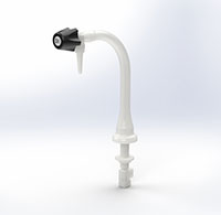
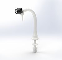
Typical Installation & Scope of a Marquest Duraline Recirculating Laboratory Faucet
Recirculating Lab Faucet System Design Notes & Specification
Duraline Recirculating Lab Faucets
The Marquest Scientific Recirculating Lab Faucet is designed primarily for use with a recirculating system which incorporates a non-pressurized storage tank or reservoir. The non-pressurized tank provides the pressure drop for the recirculating flow to continue and return via the recirculating tube. Since the water is returned to the tank, it is not actually consumed.
The objective is to provide a constant flow of DI Water when the point-of-use dispense is not being utilized. This will prevent stagnation of the water and subsequent development of bacterial growth. Continuous flow is one method of combating bacterial growth in UPW systems.
Ideally, the flow rate of the recirculating flow stream is 4.5 feet per second or greater. When utilizing the .125" ID recirculating tube, a flow rate of .2 GPM through the tube will generate a flow velocity of 5.2 feet per second.
Maintaining this flow rate will prevent bacteria and other biomass from adhering to internal surfaces. Lower flow rates are still beneficial over a stagnate system.
When piping the recirculating lab faucet in series, a common return line may be used to accept each individual recirculating tube. A small pressure drop down stream of each faucet may be necessary to assure a positive flow through the recirculating system and provide adequate pressure for the main water dispensing.
1.0 Recirculating Lab Faucet
- Recirculating Laboratory Faucet shall be constructed of polyvinylidene flouride (PVDF) or natural polypropylene (PPN) and designed to provide a continual fluid flow to the point of use to eliminate the inherent dead leg. Faucet shall be Marquest Scientific model DL-DDR-2 (Natural Polypropylene) or DL-DDR-3 (Natural PVDF).
- Faucet to be manufactured with Duraline Control Valve for on/off flow operation and precise control, featuring an encapsulated PTFE shut off seal for constant on/off use and a compression PTFE stem seal. A renewable cartridge shall be available for the valve which provides an easy method of replacing all valve moving parts while the faucet is in its installed position.
- Recirculating laboratory faucets when installed in a series require a small pressure drop to be created between the main loop supply connection and the recirculating return line connection. This may be accomplished with a common, diverter type tee fitting, a valve or an orifice plate.
- Pressure rating shall be 120 PSI.
2.0 Installation
-
System components for installation shall be of like materials of construction. Joining techniques shall confirm to best practice given the application and specifications.


 /Asset/DL-DDR-2.jpg
  /Asset/DL-DDR-2_4.jpg

